
In this post, I will continue right from where I stopped in the part 1 of this topic, how to implement Cisco l3 mpls to connect four customer branch offices. In part 1, I configured IP adresses on all physical interfaces and a loopback interface on the P router and all PE routers, and configured ospf for reachability. You can read the part one here.
In this post, I will enable mpls globally on the P router and on all PE routers. Mpls will also be enabled on the interfaces that are part of the service provider’s label switching path (LSP). For redundancy purpose, each PE router should have three LSPs to each of our customer’s branch office.
Core-P
core(config)#mpls ip

core(config)#int g1/0

core(config-if)#mpls ip

core(config-if)#int g2/0

core(config-if)#mpls ip

core(config-if)#int g3/0

core(config-if)#mpls ip

core(config-if)#int g4/0

core(config-if)#mpls ip
PHC-PE
PHC-PE(config)#mpls ip

PHC-PE(config)#int g1/0

PHC-PE(config-if)#mpls ip

PHC-PH(config-if)#int g2/0

PHC-PE(config-if)#mpls ip

PHC-PE(config-if)#int g3/0

PHC-PE(config-if)#mpls ip
LAG-PE
LAG-PE(config)#mpls ip

LAG-PE(config-if)#int g1/0

LAG-PE(config-if)#mpls ip

LAG-PE(config-if)#int g2/0

LAG-PE(config-if)#mpls ip

LAG-PE(config-if)#int g3/0

LAG-PE(config-if)#mpls ip
KAN-PE
KAN-PE(config)#mpls ip

KAN-PE(config)#int g1/0

KAN-PE(config-if)#mpls ip

KAN-PE(config-if)#int g2/0

KAN-PE(config-if)#mpls ip

KAN-PE(config-if)#int g3/0

KAN-PE(config-if)#mpls ip
ABJ-PE
ABJ-PE(config)#mpls ip

ABJ-PE(config)#int g1/0

ABJ-PE(config-if)#mpls ip

ABJ-PE(config-if)#int g2/0

ABJ-PE(config-if)#mpls ip

ABJ-PE(config-if)#int g3/0

ABJ-PE(config-if)#mpls ip
At this point, we should have ldp neighorship established with other mpls routers. We can verify this with the sh mpls ldp neighbor command. See result below.
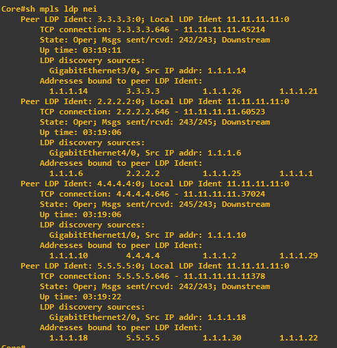
Did you notice that mpls was not enabled on the interfaces connected to the CE routers and on the CE routers themselves? This is simply because it not required.
Also read: How to configure Cisco l2tpv3 to connect two offices using GNS3
Next step is to configure Multiprotocol bgp on all PE routers. This will allow them forward vpn4 traffic from one customer site to another. mBGP is only enabled on provider edge routers. See steps below.
PHC-PE
PHC-PE(config)#router bgp 65535

PHC-PE(config-router)#neighbor 3.3.3.3 remote-as 65535

PHC-PE(config-router)#neighbor 3.3.3.3 update-source Loopback0

PHC-PE(config-router)#neighbor 4.4.4.4 remote-as 65535

PHC-PE(config-router)# neighbor 4.4.4.4 update-source Loopback0

PHC-PE(config-router)#neighbor 5.5.5.5 remote-as 65535

PHC-PE(config-router)#neighbor 5.5.5.5 update-source Loopback0

PHC-PE(config-router)# address-family vpnv4

PHC-PE(config-router-af)#  neighbor 3.3.3.3 activate

PHC-PE(config-router-af)#  neighbor 3.3.3.3 send-community extended

PHC-PE(config-router-af)#  neighbor 4.4.4.4 activate

PHC-PE(config-router-af)#   neighbor 4.4.4.4 send-community extended

PHC-PE(config-router-af)#  neighbor 5.5.5.5 activate

PHC-PE(config-router-af)#  neighbor 5.5.5.5 send-community extended
First, I enabled ibgp, then went into the vpn4 address family and enabled extended community which essentially enables the PE routers to advertise vpn4 routes through their ibgp connections. Without this a PE router will not be able to learn routes from other PE routers’ vrf tables. To establish mbgp neighborship, ibgp relationship must first be setup.
LAG-PE
LAG-PE(config)#router bgp 65535

LAG-PE(config-router)#neighbor 2.2.2.2 remote-as 65535

LAG-PE(config-router)#neighbor 2.2.2.2 update-source Loopback0

LAG-PE(config-router)#neighbor 4.4.4.4 remote-as 65535

LAG-PE(config-router)# neighbor 4.4.4.4 update-source Loopback0

LAG-PE(config-router)#neighbor 5.5.5.5 remote-as 65535

LAG-PE(config-router)#neighbor 5.5.5.5 update-source Loopback0

LAG-PE(config-router)# address-family vpnv4

LAG-PE(config-router-af)#  neighbor 2.2.2.2 activate

LAG-PE(config-router-af)#  neighbor 2.2.2.2 send-community extended

LAG-PE(config-router-af)#  neighbor 4.4.4.4 activate

LAG-PE(config-router-af)#   neighbor 4.4.4.4 send-community extended

LAG-PE(config-router-af)#  neighbor 5.5.5.5 activate

LAG-PE(config-router-af)#  neighbor 5.5.5.5 send-community extended
KAN-PE
KAN-PE(config)#router bgp 65535

KAN-PE(config-router)#neighbor 2.2.2.2 remote-as 65535

KAN-PE(config-router)#neighbor 2.2.2.2 update-source Loopback0

KAN-PE(config-router)#neighbor 3.3.3.3 remote-as 65535

KAN-PE(config-router)# neighbor 3.3.3.3 update-source Loopback0

KAN-PE(config-router)#neighbor 5.5.5.5 remote-as 65535

KAN-PE(config-router)#neighbor 5.5.5.5 update-source Loopback0

KAN-PE(config-router)# address-family vpnv4

KAN-PE(config-router-af)#  neighbor 2.2.2.2 activate

KAN-PE(config-router-af)#  neighbor 2.2.2.2 send-community extended

KAN-PE(config-router-af)#  neighbor 3.3.3.3 activate

KAN-PE(config-router-af)#   neighbor 3.3.3.3 send-community extended

KAN-PE(config-router-af)#  neighbor 5.5.5.5 activate

KAN-PE(config-router-af)#  neighbor 5.5.5.5 send-community extended
ABJ-PE
ABJ-PE(config)#router bgp 65535

ABJ-PE(config-router)#neighbor 2.2.2.2 remote-as 65535

ABJ-PE(config-router)#neighbor 2.2.2.2 update-source Loopback0

ABJ-PE(config-router)#neighbor 3.3.3.3 remote-as 65535

ABJ-PE(config-router)# neighbor 3.3.3.3 update-source Loopback0

ABJ-PE(config-router)#neighbor 4.4.4.4 remote-as 65535

ABJ-PE(config-router)#neighbor 4.4.4.4 update-source Loopback0

ABJ-PE(config-router)# address-family vpnv4

ABJ-PE(config-router-af)#  neighbor 2.2.2.2 activate

ABJ-PE(config-router-af)#  neighbor 2.2.2.2 send-community extended

ABJ-PE(config-router-af)#  neighbor 3.3.3.3 activate

ABJ-PE(config-router-af)#   neighbor 3.3.3.3 send-community extended

ABJ-PE(config-router-af)#  neighbor 4.4.4.4 activate

ABJ-PE(config-router-af)#  neighbor 4.4.4.4 send-community extended
At this stage, we should have ibgp neigbor relationship established to support vpn4. Even the core router at the middle is not running bgp, we should be able to establish ibgp peering between PHC-PE and ABJ-PE. With regards to this setup, the core router is referred to as transit router because we have bgp relationship formed over it.
We can verify this with two commands. First, the sh ip bgp summary command. See output from PHC-PE router below:

We can also use the sh bgp nei command on PHC-PE to see the capability table of these neighbor relationship. See ouput below:
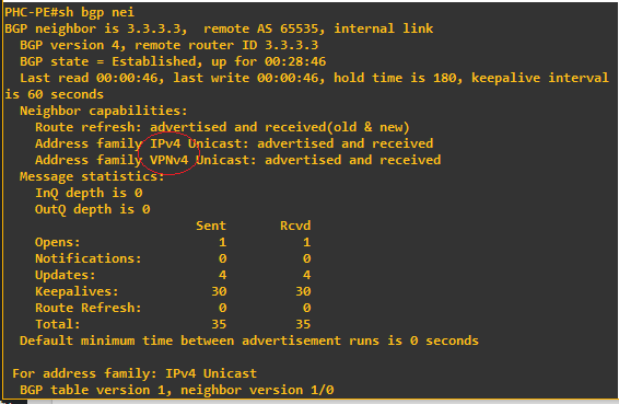 We can see from the image above that both ipv4 and vpnv4 capabilities are supported for the peering to 3.3.3.3 which is the loopback address on LAG-PE router. Same applies for other ibgp neighbors.
In my next post, which should be the final for this lab, I will set up virtual routing and forwarding between PE and CE routers and implement redistribution between ospf running in the VRFs and bgp. Those are the remaining configurations needed to provide full connectivity for our customer to reach all his branches.
You can read the final part of this post here
If you enjoyed this tutorial, please subscribe to this blog to receive my posts via email. Also subscibe to my YouTube channel, like my Facebook page and follow me on Twitter.