Static route is awesome if you know what you are doing. An excellent implementation of static route on your network puts you in total control of your routing table, making sure there are no rooms for any neighbor routers to goof up your routing table and cause unimaginable problems on your network. In this demonstration, we will be looking at one of the first network designs you are presented with when studying routing in the CCNA series.
The topology involves three routers with two WAN links and three local area networks between them. The objective is to achieve full connectivity among all the hosts on all the networks, using static route.
What you should commit to memory about static route:
>>It has a default administrative distance of 1
>>It supports variable length subnetmask and classless addressing
>>Networks/subnets must be statically configured on all routers
>>It’s supported across all vendors’ equipment
>>It does not use your bandwidth for route advertisement
>>Implementing static route on a large network can be tasking though not impossible
Read: Use Cisco router to redirect dns requests to a local dns server
Network Topology:

Using the Cisco Packet Tracer, select three Cisco 2811 routers, three 2960 Cisco Catalyst switches, and six desktop computers. To get the serial connections, click on the router, click on physical, switch off the router, click and drag the WIC-1T module to one of the expansion slots. For router1, I added two modules of WIC-1T because router1 has two serial connections. The image below shows how it is added.

Implementation
On Router0: I will configure both the serial and f0/0 interfaces, implement static routes to get to the three networks that are unknown to Router0, namely: networks 192.168.0.4/30, 192.168.2.0/24 and 192.168.3.0/24. See commands below:
Router(config)#hostname Router0
Router0(config)#int s0/3/0
Router0(config-if)#ip add 192.168.0.1 255.255.255.252
Router0(config-if)#description connection-to-Router1
Router0(config-if)#no shut
Router0(config-if)#int f0/0
Router0(config-if)#ip add 192.168.1.1 255.255.255.0
Router0(config-if)#desc connection-to-LAN
Router0(config-if)#no shut
Router0(config-if)#exit
Router0(config)#ip route 192.168.0.4 255.255.255.252 192.168.0.2
Router0(config)#ip route 192.168.2.0 255.255.255.0 192.168.0.2
Router0(config)#ip route 192.168.3.0 255.255.255.0 192.168.0.2
Router(config)#hostname Router1
Router1(config)#int s0/3/0
Router1(config-if)#ip add 192.168.0.2 255.255.255.252
Router1(config-if)#description connection-to-Router0
Router1(config-if)#clock rate 64000
Router1(config-if)#no shut
Router1(config)#int s0/1/0
Router1(config-if)#ip add 192.168.0.5 255.255.255.252
Router1(config-if)#description connection-to-Router2
Router1(config-if)#clock rate 64000
Router1(config-if)#no shut
Router1(config-if)#int f0/0
Router1(config-if)#ip add 192.168.2.1 255.255.255.0
Router1(config-if)#desc connection-to-LAN
Router1(config-if)#no shut
Router1(config-if)#exit
Router1(config)#ip route 192.168.2.0 255.255.255.0 192.168.0.1
Router1(config)#ip route 192.168.3.0 255.255.255.0 192.168.0.6
Router(config)#hostname Router2
Router2(config)#int s0/3/0
Router2(config-if)#ip add 192.168.0.6 255.255.255.252
Router2(config-if)#description connection-to-Router1
Router2(config-if)#no shut
Router2(config-if)#int f0/0
Router2(config-if)#ip add 192.168.3.1 255.255.255.0
Router2(config-if)#desc connection-to-LAN
Router2(config-if)#no shut
Router2(config-if)#exit
Router2(config)#ip route 192.168.0.0 255.255.255.252 192.168.0.5
Router2(config)#ip route 192.168.1.0 255.255.255.0 192.168.0.5
Router2(config)#ip route 192.168.2.0 255.255.255.0 192.168.0.5
Verification
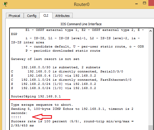
To verify, we need to look at the routing tables of the routers using the sh ip route command. Below is the output of the command on router0:
From the output above, we can see that router0 has route entries for networks 192.168.0.4/30, 192.168.2.0/24, and 192.168.3.0/24. These routes were learned from router1 (192.168.0.2) using static routes, hence, the S symbol, and they all have the default administrative distance of 1. Let’s run a ping from router0 to the LAN interface on router2 (192.168.3.1)
.