
Mikrotik eiop is a Mikrotik proprietary protocol that is to Mikrotik what DMVPN is to Cisco. While majority have heard of the Mikroti eoip, only a few understands its practical implementation. In this Lab, I will be sharing with us on how to deploy eiop in a hub and spoke topology to connect multiple branch offices to the HQ.
If you are a network administrator, administering networks with many branch offices that are connected together via an ISP circuit, chances are that your ISP is using Mikrotik eoip, Cisco dmvpn or mpls to link your branches. In this demonstration, we will be connecting three branch offices to the HQ. Since we are using physical interfaces, the number of sites will be a determining factor in choosing the type of Mikrotik router that will used for this project. With that in mind, I will be using the RB750 with 5 dedicated ports. The eoip router (RB750) are configured and managed by the ISP. This demonstration shows want goes on in that ISP cloud.
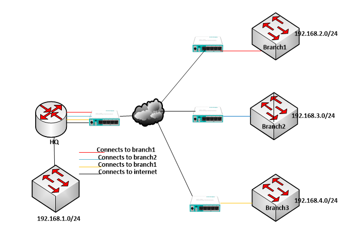
Network Topology
Lab objective
Use eoip to provide our client with a circuit that connects all three branches to the HQ. Our solution will aid on file sharing and collaboration among offices, reduce operational expenses and help increase productivity.
Mikrotik EOIP Implementation.
On the hub (Mikrotik RB750 attached to the HQ), we will configure ether2 to provide internet at the HQ, ether3 will be layer2 connection to branch1, ether4 will provide layer2 connection to branch2, and ether5 will be configured to provide layer2 connection to branch3. See commands below:
[admin@Hub] > ip add add address=201.2.2.1/30 interface=ether2 comment=internet_at_HQ
[admin@Hub] >ip route add dst=0.0.0.0 gateway=ether1
Next, Mikrotik eoip configuration on the Hub.
Configuring Mikrotik eoip on the hub to connect multiple bracches
[admin@Hub] interface eoip> add name=”eoip-to-branch1″ tunnel-id=10 remote-address=1.1.1.2
[admin@Hub] interface eoip> enable eoip-to-branch1
[admin@Hub] interface eoip> add name=”eoip-to-branch2″ tunnel-id=20 remote-address=2.2.2.2
[admin@Hub] interface eoip> enable eoip-to-branch2
[admin@Hub] interface eoip> add name=”eoip-to-branch3″ tunnel-id=30 remote-address=3.3.3.2
[admin@Hub] interface eoip> enable eoip-to-branch3
Next, we create bridges and add an eiop interface and the corresponding ports on the RB750 to each bridge. See below.
[admin@Hub] interface bridge> add name=bridge1
[admin@Hub] interface bridge> port add bridge=bridge1 interface=eoip-to-branch1
[admin@Hub] interface bridge> port add bridge=bridge1 interface=ether3
[admin@Hub] interface bridge> add name=bridge2
[admin@Hub] interface bridge> port add bridge=bridge1 interface=eoip-to-branch2
[admin@Hub] interface bridge> port add bridge=bridge1 interface=ether4
[admin@Hub] interface bridge> add name=bridge3
[admin@Hub] interface bridge> port add bridge=bridge1 interface=eoip-to-branch3
[admin@Hub] interface bridge> port add bridge=bridge1 interface=ether5
Next is to configure the spokes at all branches.
EOIP configuration on Spoke1
[admin@spoke1] interface eoip> add name=”eoip-to-HQ” tunnel-id=10 remote-address=1.1.1.1
[admin@Spoke1] interface eoip> enable eoip-to-HQ
[admin@Spoke1] interface bridge> add name=bridge1
[admin@Spoke1] interface bridge> port add bridge=bridge1 interface=eoip-to-HQ
[admin@Spoke1] interface bridge> port add bridge=bridge1 interface=ether2
Eiop configuration on Spoke2
[admin@spoke2] interface eoip> add name=”eoip-to-HQ” tunnel-id=20 remote-address=2.2.2.1
[admin@Spoke2] interface eoip> enable eoip-to-HQ
[admin@Spoke2] interface bridge> add name=bridge1
[admin@Spoke2] interface bridge> port add bridge=bridge1 interface=eoip-to-HQ
[admin@Spoke2] interface bridge> port add bridge=bridge1 interface=ether2
Eiop configuration on Spoke3
[admin@spoke3] interface eoip> add name=”eoip-to-HQ” tunnel-id=30 remote-address=3.3.3.1
[admin@Spoke3] interface eoip> enable eoip-to-HQ
[admin@Spoke3] interface bridge> add name=bridge1
[admin@Spoke3] interface bridge> port add bridge=bridge1 interface=eoip-to-HQ
[admin@Spoke3] interface bridge> port add bridge=bridge1 interface=ether2
Note that on the spoke routers, ether1 is configured to connect to the ISP cloud while ether2, shown in the configuration is used to deliver layer2 services.
Finally, we configure the HQ router to provide connectivities to all branches via the ISP-delivered layer2 links. Four cables will be dropped by the ISP at the HQ; one for internet (layer3) and three for layer2 connectivities to be branches.
[admin@HQ] > ip add add address=201.2.2.2/30 interface=ether1 comment=layer3-link
[admin@HQ] >ip route add dst=0.0.0.0 gateway=ether1
[admin@HQ] > ip firewall nat add out-interface=ether1 action=masquerade
[admin@HQ] > ip add add address=192.168.1.1/24 interface=ether2 comment=HQ_LAN
[admin@HQ] > ip add add address=192.168.2.1/24 interface=ether3 comment=Branch1_LAN
[admin@HQ] > ip add add address=192.168.3.1/24 interface=ether4 comment=Branch2_LAN
[admin@HQ] > ip add add address=192.168.4.1/24 interface=ether5 comment=Branch3_LAN
We will also configre dhcp servers on the HQ to provide IP addresses for hosts on the HQ LAN and those connected to the switches at all branches.
DHCP Configuration on the HQ router
At this stage, we configure four dhcp servers to handle IP address leasing for HQ_LAN and all brach offices networks. See below.
[admin@HQ] ip dhcp-server> setup
Select interface to run DHCP server on
dhcp server interface: ether2
Select network for DHCP addresses
dhcp address space: 192.168.1.0/24
Select gateway for given network
gateway for dhcp network: 192.168.1.1
Select pool of ip addresses given out by DHCP server
addresses to give out: 192.168.1.2-192.168.1.254
Select DNS servers
dns servers: 192.168.1.1
Select lease time
lease time: 3d
[admin@HQ] ip dhcp-server>
Repeat steps for the branch offices.