
The Cisco DMVPN, full name, dynamic mutipoint VPN has been around for years, allowing businesses to dynamically connect branch offices to headqaurters in a hub and spoke or full meshed setup. Cisco DMVPN provides full meshed connectivity with simplified hub and spoke configuration and supports what Cisco refers to as “zero-touch” configuration for the addition of new spokes.
Cisco DMVPN uses IPsec and GRE to set up a virtual circuit between multiple locations over the internet in an easy, dynamic, and scalable manner. The technology relies on Next Hop Resolution Protocol (NHRP) and Multipoint GRE tunnel interface. In a simple term, it allows you to create a single tunnel interface and use it to reach multiple locations. How is that possible? Well by using a dynamic routing protocol like eigrp, ospf, BGP, and RIPv2. In this demonstration, starting with a hub-and-spoke approach, I will share with us on how to connect two branches to the HQ. Addition of more spokes (branch offices) is straight forward and simple with no modification required on the Hub (HQ).
Network Topology

Objective
The objective of this lab is to creat a a virtual circuit over the public internet, using Cisco DMVPN, through which the LANs on R1, R2, and R3 can communicate. The communication between R2 and R3 will only be possible through R1. R4 represents the internet and as such, will not participate in eigrp. Secured connection between offices, using IPsec is not part of this LAB, though it can be used with DMVPN. That will be treated in another demonstration.
IP address configuration on R4
R4(Config)#interface FastEthernet0/0
R4(Config-if)#ip address 100.1.1.1 255.255.255.252
R4(Config-if)#desc connection_to_R1
R4(Config-if)#no shut
R4(Config-if)#interface FastEthernet0/1
R4(Config-if)#ip address 200.1.1.1 255.255.255.252
R4(Config-if)#desc connection_to_R2
R4(Config-if)#no shut
R4(Config-if)#interface FastEthernet1/0
R4(Config-if)#ip address 203.1.1.1 255.255.255.252
R4(Config-if)#desc connection_to_R3
R4(Config-if)#no shut
That is all we need to do on R4. Note that the configuration on R4 is not required in real life as that will be the job of the ISP. Next is to configure the Hub, which in this case is R1 (HQ).
Cisco DMVPN configuration on the Hub router (R1)
(config)#interface Loopback0
(config-if)#ip address 1.1.1.1 255.255.255.255
(config-if)#interface Tunnel0
(config-if)# ip address 192.168.1.1 255.255.255.0
(config-if)# ip nhrp authentication timigate
(config-if)#ip nhrp map multicast dynamic
(config-if)#ip nhrp network-id 25
(config-if)#tunnel source FastEthernet0/0
(config-if)#tunnel mode gre multipoint
(config-if)#interface FastEthernet0/0
(config-if)# ip address 100.1.1.2 255.255.255.252
(config-if)#no shut
(config-if)#exit
(config)#router eigrp 25
(config-router)#router eigrp 25
(config-router)#network 1.0.0.0
(config-router)#network 192.168.1.0
(config-router)#no auto-summary
(config-router)#exit
(config)#ip route 200.1.1.0 255.255.255.252 100.1.1.1 (this allows R1 to form eigrp neighbor relationship with R2 not need in live network as ISP will take care of that)
(config)#ip route 203.1.1.0 255.255.255.252 100.1.1.1 (this allows R1 to form eigrp neighbor relationship with R2, again, not need in live network as ISP will take care of that)
Cisco DMVPN configuration on R2
(config)#interface Loopback0
(config-if)#ip address 2.2.2.2 255.255.255.255
(config-if)#interface Tunnel0
(config-if)#ip address 192.168.1.2 255.255.255.0
(config-if)#ip nhrp authentication timigate
(config-if)#ip nhrp map 192.168.1.1 100.1.1.2
(config-if)#ip nhrp map multicast 100.1.1.2
(config-if)#ip nhrp network-id 25
(config-if)#ip nhrp nhs 192.168.1.1
(config-if)#tunnel source FastEthernet0/0
(config-if)#tunnel destination 100.1.1.2
(config-if)# interface FastEthernet0/0
(config-if)# ip address 200.1.1.2 255.255.255.252
(config-if)#exit
(config)#router eigrp 25
(config-router)#network 2.2.2.2 0.0.0.0
(config-router)#network 192.168.1.0
(config-router)#no auto-summary
(config)#exit
(config)#ip route 100.1.1.0 255.255.255.252 200.1.1.1 (allows R2 to form eigrp neighbor relaship with R1 and R3. Not needed on a live network as ISP would have taken care of that.)
You may also like: How to configure Cisco l2tpv3 to connect two offices using GNS3
Configuration on R3
(config)#interface Loopback0
(config-if)#ip address 3.3.3.2 255.255.255.255
(config-if)#interface Tunnel0
(config-if)#ip address 192.168.1.3 255.255.255.0
(config-if)#ip nhrp authentication timigate
(config-if)#ip nhrp map 192.168.1.1 100.1.1.2
(config-if)#ip nhrp map multicast 100.1.1.2
(config-if)#ip nhrp network-id 25
(config-if)#ip nhrp nhs 192.168.1.1
(config-if)#tunnel source FastEthernet0/0
(config-if)#tunnel destination 100.1.1.2
(config-if)# interface FastEthernet0/0
(config-if)# ip address 203.1.1.2 255.255.255.252
(config-if)#exit
(config)#router eigrp 25
(config-router)#network 3.3.3.2 0.0.0.0
(config-router)#network 192.168.1.0
(config-router)#no auto-summary
(config)#exit
(config)#ip route 100.1.1.0 255.255.255.252 203.1.1.1
Verification
First, we need to be sure that eigrp neighbor relationships have been formed. Lets check with the sh ip eigrp nei command on R1.
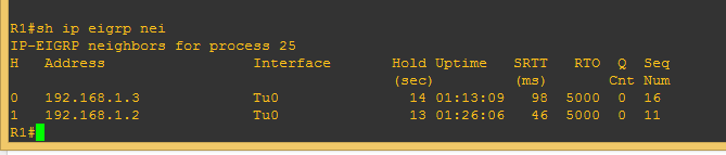
From the image above, we can see that even though R4 is not running eigrp, R1 has been able to form eigrp neighbor relationships with the two spokes (branch office routers). R2 and R3 are not direct eigrp neighbors and communication between them can only be achieved via R1. Next, let’s look at the nhrp mapping on R1
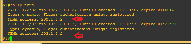
We can see from the image above that the public and tunnel addresses on R2 and R3 have been dynamically learned. The public IP configured on the physical interface is listed as Non-broadcast multi access (NBMA). Lets see the routing table of R3.
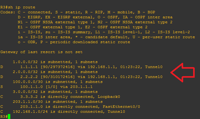
We can see that R3 has entries for the loopback addresses (LAN) on R1 and R2, and it shows that that of R2 can only be reached via R1. Finally, lets do a ping and trace test from R3, to R1 and R2.
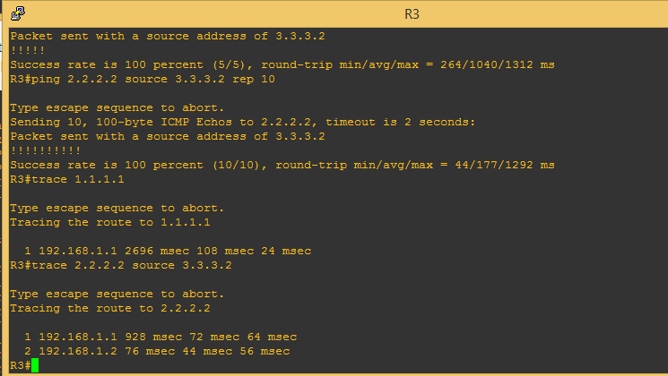
Looking at the result above, especially the traceroute, you will notice that while the trace to R1 loopback IP went straight to R1’s tunnel IP, the one to R2’s loopback IP went to R1’s tunnel IP, then to R2’s tunnel IP. This is because what I just demonstrated is not a full meshed topology. The demonstration for full meshed will be published next.
Click here to read Cisco’s documentation on DMVPN and learn about features and supported protocols.
This LAB was performed on GNS3 using four Cisco 7200 series routers. To get the LAB, kindly drop your email address in the comment box on this blog and it will be mailed to you free of charge.