
PPPoE on mikrotik vlans and Cisco switches will not only deliver optimal connectivity solutions to your customer if you are an ISP, it will save you cost while providing an easy-to-manage single pane of glass for administering your connected clients. In this article, I will try to produce a solution that mirrors an ISP setup for delivering direct internet access to users via FTTX while cutting down on CAPEX.
My PPPoE on Mikrotik Vlans will comprise of a Mikrotik Edge router (preferably a Mikrotik Cloud Core router), one or two Cisco manage switches and Mikrotik access routers (Mikrotik Rb951). The Mikrotik Cloud core router and the Cisco switches will sit at the ISP edge while the Mikrotik RB951 access routers will be deployed as customer edge routers at clients’ locations.
Cable connectedness
To be able to service multiple customers from a single port on the Mikrotik cloud core router, a trunk link will be established to a Cisco managed switch that will carry mutliple vlans; each vlan corresponding to a customer’s circuit. In a GPON FTTx setup, a trunk port will be established between the Cisco switch and an OLT from where mutiple connections will go to customer locations and terminate on ONUs. From an optical network unit (ONU) in a client’s office or home, a cable connection will terminate on a Mikrotik RB951 that will be configured as a PPPoE client.
You may also like: Mikrotik VLAN with mutiple DHCP servers
Where clients are on direct fiber to home, using media converters, a customer’s link can simply be delivered via an access port on the Cisco switch to the Mikrotik RB951 access router at the client’s location. The switch port will be configured as access port on the client’s vlan.
PPPoE on Mikrotik Vlans Configuration
To implement PPPoE on Mikrotik vlans that are trunked to a Cisco managed switch, the configuration will be done in this order: the Mikrotik edge router, the Cisco switch, and the Mikrotik access router. On the Mikrotik edge router, i will create vlans, setup a trunk port to carry vlan traffics to the switch and setup PPPoE on the vlan interfaces. On the switch, the vlans on the Mikrotik will be replicated and the switch ports would be configured accordingly with the approprate vlans passed where required. Finally, I will configure a PPPoE client on the WAN interface of the Mikrotik RB951 access router at the client’s location.
Edge router configuration
Vlans, trunk port and IP address assignment. See commands below.
/int vlan
add name=vlan10 vlan-id=10 interface=bridge1
add name=vlan10 vlan-id=11 interface=bridge1
add name=vlan10 vlan-id=12 interface=bridge1
! Create bridge for the trunk
/int bridge
add name=bridge1
port add interface=ether1 bridge=bridge1
vlan add vlan-ids=10 bridge=bridg1 untagged=bridge1
vlan add vlan-ids=11 bridge=bridg1 untagged=bridge1
vlan add vlan-ids=12 bridge=bridg1 untagged=bridge1
! Assign IP addresses to the vlan interfaces
/Ip address
Add address=192.168.10.1/24 interface=vlan10
Add address=192.168.11.1/24 interface=vlan11
Add address=192.168.12.1/24 interface=vlan12
PPPoE server configuration for all three clients. This consists of address pool, PPP profile and secret configurations. See commands below.
/Ip pool
add name=PPPoE_client1 range=192.168.10.2-192.168.10.254
add name=PPPoE_client2 range=192.168.11.2-192.168.11.254
add name=PPPoE_client3 range=192.168.12.2-192.168.12.254
!create PPP profile for all three clients!
/ppp profile
add name=PPPoE_client1 local-address=192.168.10.1 remote-address=PPPoE_cleint1 dns-server=8.8.8.8
add name=PPPoE_client2 local-address=192.168.11.1 remote-address=PPPoE_cleint2 dns-server=8.8.8.8
add name=PPPoE_client3 local-address=192.168.12.1 remote-address=PPPoE_cleint3 dns-server=8.8.8.8
!Create PPP secret for all three clients
ppp secret
add name=client1 password=admin@123 profile=PPPoE_client1 service-pppoe
add name=client2 password=admin@123 profile=PPPoE_client2 service-pppoe
add name=client3 password=admin@123 profile=PPPoE_client3 service-pppoe
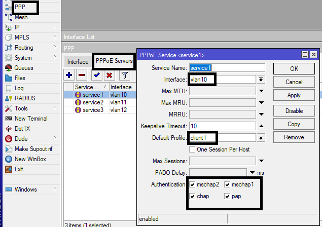
Finally on the PPPoE server side, we enable PPPoE server on the vlan interfaces. Repeat for all vlans. See in the image below.
Cisco switch configuration
The uplink port on the switch will be configured as trunk, vlans 10,11, and 12 will be created and allowed on the trunk, access ports will be configured to access vlans 10, 11, and 12 on the ports that link the switch to the Mikrotik RB951 access routers at customer locations. See switch configuration commands below.
vlan 10
name client1
vlan 11
name client2
vlan 12
name client3
int g0/0
sw trunk en dot1q
sw mode trunk
sw trunk allow vlan 10,11,12
int g0/1
sw mode access
sw access vlan 10
g0/2
sw mode access
sw access vlan 11
int g0/3
sw mode access
sw access vlan 12
PPPoE Client Configuration
Finally, we configure PPPoE client on the uplink interfaces on the Mikrotik RB951 access routers at clients locations. The configuration is simple. See below.
int pppoe-c add interface=ether1 user=client1 password=admin@123
PPPoE on vlans connected clients
Below are the connected clients. The list can be accessed via the terminal with the command “ppp active print” or via GUI by click on active connections in the ppp tab.

Below is a video on my YouTube channel on how to accomplish the same task:
If you enjoyed this tutorial, please subscribe to this blog to receive my posts via email. Also subscribe to my YouTube channel, like my Facebook page and follow me on Twitter.