
If you are reading this post and you desire to implement layer 2 mpls with l2tpv3 for transparent bridging between two locations, then you are at the right place. In this post, I will share with us on how internet service providers transparently connect two customer sites over an mpls circuit with l2tpv3.
Because a layer 2 mpls connection allows customers to choose their private IP addresses, this lab has been designed to address the situation where two or more customers have the same private subnet across different locations.
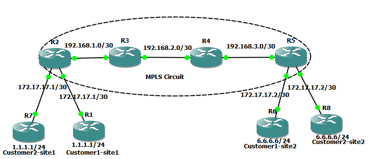
Network topology
Objective of LAB
The objective of this lab is to mplemnt layer2 mpls with l2tpv3 to provide layer 2 connectivity between the two locations of Customer1 and Customers2. Even though they are both using the same private subnets for their WAN and private network, our layer 2 implementation should be intelligent enough to take care of this situation by ensuring that traffics between both locations do not mix.
MPLS and IP address configuration
Here, I will assign IP addresses, enable mpls globally and on participating interfaces provider and provider-edge routers. My provider routers are Router3 and Router4 while Router2 and Router5 are my Provider-Edge routers.
You may also like: How to implement Cisco L3 MPLS to connect four customer branches
Router 2
conf t
 mpls ip
 int g2/0
 ip add 192.168.1.1 255.255.255.0
 mpls ip
 no shut
 int l0
 ip add 2.2.2.2 255.255.255.255
 exit
 router ospf 1
 netw 192.168.1.0 0.0.0.255 area 0
 netw 2.2.2.2 0.0.0.0 area 0
 end
 wr
Router 3
conf t
 mpls ip
 int g1/0
 ip add 192.168.1.2 255.255.255.0
 mpls ip
 no shut
 int g2/0
 ip add 192.168.2.1 255.255.255.0
 mpls ip
 no shut
 int l0
 ip add 3.3.3.3 255.255.255.255
 exit
 router ospf 1
 netw 192.168.1.0 0.0.0.255 area 0
 netw 192.168.2.0 0.0.0.255 area 0
 netw 3.3.3.3 0.0.0.0 area 0
 end
 wr
Router 4
conf t
 mpls ip
 int g1/0
 ip add 192.168.2.2 255.255.255.0
 mpls ip
 no shut
 int g2/0
 ip add 192.168.3.1 255.255.255.0
 mpls ip
 no shut
 int l0
 ip add 4.4.4.4 255.255.255.255
 exit
 router ospf 1
 netw 192.168.2.0 0.0.0.255 area 0
 netw 192.168.3.0 0.0.0.255 area 0
 netw 4.4.4.4 0.0.0.0 area 0
 end
 wr
Router 5
conf t
 mpls ip
 int g1/0
 ip add 192.168.3.2 255.255.255.0
 mpls ip
 no shut
 int l0
 ip add 5.5.5.5 255.255.255.255
 exit
 router ospf 1
 netw 192.168.3.0 0.0.0.255 area 0
 netw 5.5.5.5 0.0.0.0 area 0
 end
 wr
At this point, we have mpls and ospf running. The loopback addresses are used for ldp neighbor relationship. We can verify mpls ldp neighbor relationship with the sh mpls forwarding-table command. See output of this command on Router2 below. Note that mpls was not enabled on interfaces connecting to customer-edge devices on the provider-edge routers. I will return both PE routers to configure theses interfaces for layer 2 transport.
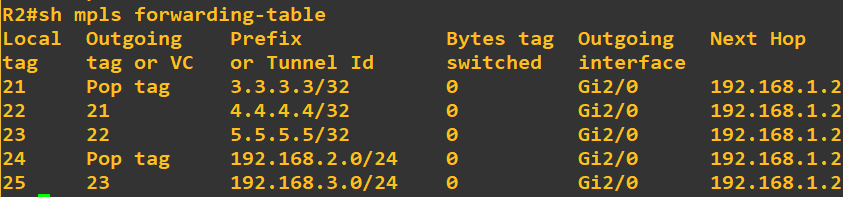
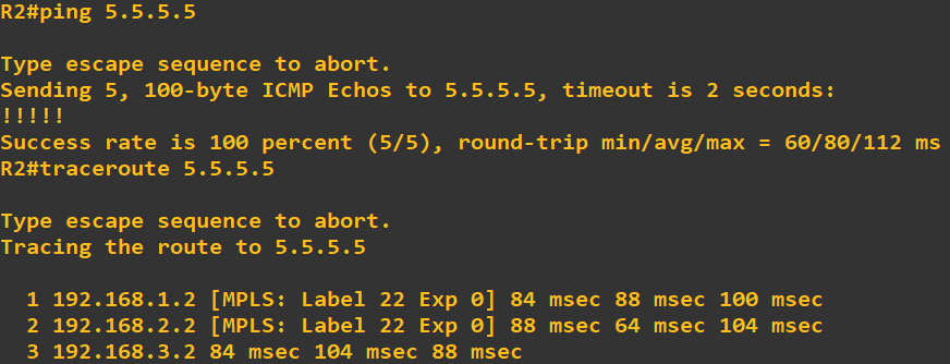
From the image above, we can see that local and outgoing tags to reach remote networks that have been advertised to Router2 via ospf. At this point, both provider-edge routers should be able to reach each other via the loopback addresses configured on them.
Configure layer 2 vpn
Since we now have mpls fully setup, the next step is to configure layer 2 vpn to ride on our mpls network. This will be done specifically on the interfaces connecting to the customer-edge devices on our provider-edge routers, in this case, Router 2 and Router 5. Mpls is not enabled on interfaces connecting to customer-edge devices.
You may like: Cisco DMVPN setup for connecting branch offices, ATM and POS to HQ
Router 2
conf t
 pseudowire-class PHC
 encapsulation l2tpv3
 ip local interface Loopback0
 exit
 int g1/0
 desc connection to Customer1_site1
 xconnect 5.5.5.5 1 pw-class PHC
 no shut
 int g3/0
 desc connection to Customer2_site1
 xconnect 5.5.5.5 2 pw-class PHC
 no shut
 end
 wr
Router 5
conf t
 pseudowire-class LAG
 encapsulation l2tpv3
 ip local interface Loopback0
 exit
 int g2/0
 desc connection to Customer1_site2
 xconnect 2.2.2.2 1 pw-class LAG
 no shut
 int g3/0
 desc connection to Customer2_site2
 xconnect 2.2.2.2 2 pw-class LAG
 no shut
 end
 wr
Note: I created a pseudo-wire class and set the encapsulation to l2tpv3 and then used the pseudo-class to configure my xconnect, making sure that my circuit ID remains the same across both PE routers for a given circuit. Customer1_site1 uses circuit ID 1 to get to Customer1_site2 while Customer2_site1 uses circuit ID 2 to get to Customer2_site2. This ensures that packets are not mixed up even though both clients are using same private subnets. Also note that no ip addresses were configured on these interfaces.
IP configuration and routing on Customer routers
Finally, we configure IP addresses on customer routers as well as routing to advertise networks across the layer 2 links.
Customer1_site1
conf t
 int g1/0
 ip add 172.17.17.1 255.255.255.252
 no shut
 int l0
 ip add 1.1.1.1 255.255.255.0
 exit
 router eigrp 1
 netw 172.17.17.0
 netw 1.1.1.0
 no auto
 end
 wr
Customer1_site2
conf t
 int g1/0
 ip add 172.17.17.2 255.255.255.252
 no shut
 int l0
 ip add 6.6.6.6 255.255.255.0
 exit
 router eigrp 1
 netw 172.17.17.0
 netw 6.6.6.0
 no auto
 end
 wr
Customer2_site1
conf t
 int g1/0
 ip add 172.17.17.1 255.255.255.252
 no shut
 int l0
 ip add 1.1.1.1 255.255.255.0
 exit
 router eigrp 1
 netw 172.17.17.0
 netw 1.1.1.0
 no auto
 end
 wr
Customer2_site2
conf t
 int g1/0
 ip add 172.17.17.2 255.255.255.252
 no shut
 int l0
 ip add 6.6.6.6 255.255.255.0
 exit
 router eigrp 1
 netw 172.17.17.0
 netw 6.6.6.0
 no auto
 end
 wr
We are done! Layer2 mpls with l2tpv3 configured! Did you notice how our customers are able to run eigrp over the mpls network even though our mpls routers are not running eigrp? Isn’t that awesome? For the records, customers can run any routing protocol of their choice. Be it ospf, eigrp, rip or bgp.
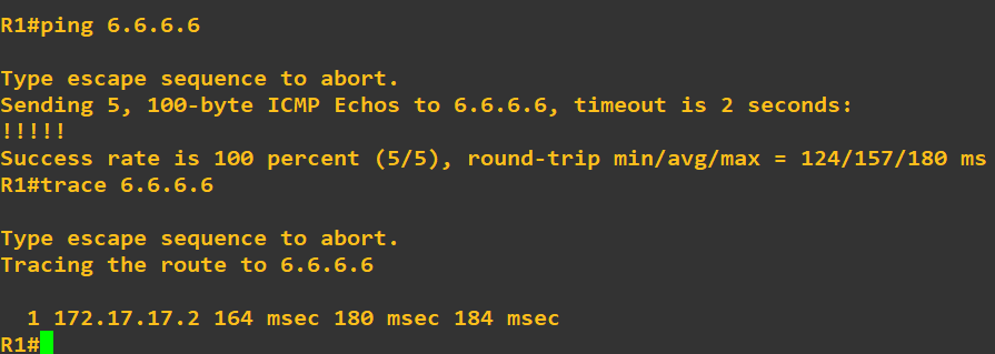
If you followed up to this point, congratulations! I should be able to ping 6.6.6.6 from both Cutsomer1_site1 and Customer2_site2. The question is, how do you know you are reaching the right site. To be sure, shut down Customer2_site2 and you will observe that 6.6.6.6 and 172.17.17.2 will become unreachable from Customer2_site1 even though same IPs are reachable from Customer1_site1. Traceroute to 6.6.6.6 should display 172.17.17.2 as the only hop.
If you enjoyed this tutorial on layer2 mpls with l2tpv3, please subscribe to this blog to receive my posts via email. Also subscibe to my YouTube channel, like my Facebook page and follow me on Twitter.
1 thought on “Cisco layer2 MPLS with l2tpv3 implementation made easy”