With PPP multilink, users can bundle multiple leased lines into one with the combined capacity of all participating links, and load-balance across the link.
In this simple demonstration, I will share with us on how to combine three leased lines, each with 1mbps bandwidth, into one link with a combined capacity of 3mbps.
The lab will be configured on gns3 with three units of the Cisco 3745 router. Each of the routers has three serial ports for ppp connection to remote location.
In today’s world where mpls has become the darling of the industry, you probably may not need this, however, if you are a candidate for CCNA, Cisco expects you to know it. So, let’s get this over with!
Network topology

PPP Multilink implementation
The implementation of this lab is pretty simple. On each router, we will enable the three participating physical interfaces without setting IPs on them, enable PPP encapsulation on them, create a multilink interface on each router and assign the three physical interfaces to the multilink interface and finally, assign an IP address to the multilink interface.
On Router3
The first step is to enable PPP multilink interface and assign an IP address to it. See steps below.
Router3(config)#interface Multilink 1

Router3(config-if)#ip address 172.17.17.1 255.255.255.252

Router3(config-if)#ppp multilink

Router3(config-if)#ppp multilink group 1
Next, we enable PPP encapsulation on the physical interfaces, enable them and assign them to the multilink group 1 created above.
Router3(config)#interface Serial0/0

Router3(config-if)#no ip address

Router3(config-if)#encapsulation ppp

Router3(config-if)#no shut

Router3(config-if)#ppp multilink

Router3(config-if)#ppp multilink group 1

Router3(config-if)#interface Serial0/1

Router3(config-if)#no ip address

Router3(config-if)#encapsulation ppp

Router3(config-if)#no shut

Router3(config-if)#ppp multilink

Router3(config-if)#ppp multilink group 1

Router3(config-if)#interface Serial0/2

Router3(config-if)#no ip address

Router3(config-if)#encapsulation ppp

Router3(config-if)#no shut

Router3(config-if)#ppp multilink

Router3(config-if)#ppp multilink group 1
Finally, we create a loopback interface to represent the LAN and configure static route or any IGP for LAN-to-LAN reachability across the PPP Multilink. See below.
Router3(config)#interface Loopback0

Router3(config-if)#ip address 10.10.0.1 255.255.0.0

Router3(config-if)#exit

Router3(config)#ip route 10.20.0.0 255.255.0.0 172.17.17.2
Having gotten to this point, we proceed to Router1 and repeat the steps above using the corresponding interfaces and IP addresses.
Also read: How to implement eigrp on a network topology with three Cisco routers
On Router1
Router1(config)#interface Loopback0

Router1(config-if)#ip address 10.20.0.1 255.255.0.0

Router1(config)#interface Multilink1

Router1(config-if)#ip address 172.17.17.2 255.255.255.252

Router1(config-if)#ppp multilink

Router1(config-if)#ppp multilink group 1

Router1(config)#interface Serial0/0

Router1(config-if)#no ip address

Router1(config-if)#encapsulation ppp

Router1(config-if)#no shut

Router1(config-if)#ppp multilink

Router1(config-if)#ppp multilink group 1

Router1(config)#interface Serial0/1

Router1(config-if)#no ip address

Router1(config-if)#encapsulation ppp

Router1(config-if)#no shut

Router1(config-if)#ppp multilink

Router1(config-if)#ppp multilink group 1

Router1(config)#interface Serial0/2

Router1(config-if)#no ip address

Router1(config-if)#encapsulation ppp

Router1(config-if)#no shut

Router1(config-if)#ppp multilink

Router1(config-if)#ppp multilink group 1

Router1(config-if)#exit

Router1(config)#ip route 10.10.0.0 255.255.0.0 172.17.17.1
Verification
The show interface multilink 1 command will show the multilink interface status. See output below.

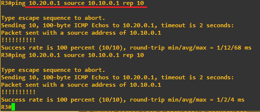
Finally, run a ping from R3 to R1’s loopback IP.

If you enjoyed this tutorial, please subscribe to this blog to receive my posts via email. Also subscibe to my YouTube channel, like my Facebook page and follow me on Twitter.
