The Border Gateway Protocol is used to share routing information between internet routers in different autonomous systems (AS) for ebgp or between routers in the same autonomous system as in the case of ibgp. If you have block of public address that you will like to advertise to the rest of the internet, then bgp is the protocol designed to help you advertise your prefix to the rest of bgp-speaking routers on the internet. In this lab, we are going to demonstrate the use of bgp from the perspective of a company that has acquired some blocks of public IPs with two leased lines from two upper providers. Our goal is to advertise our prefixes out of these two connections.
The following will be done:
* Set up ebgp peering between our AS and the two upper providers ASs
* Use default route to prefer one of our upper providers for all uploads and fail-over to the second provider in event of downtime on the preferred link.
* Create a filter rule to filter all route update from our providers so that we don’t over-stretch our router’s limited resources.
Create another filter rule to filter what we advertise to our neighbors. We do not want to accidentally advertise our internal networks.
I will try to make this as simple and as detailed as it should be. So, sit back and pay attention.
From the image above, our prefixes are configured on loopbacks and we want all our uploads to go out through R2 (ISP1) in AS 200 while load-balancing our download on both links with bulk of the download coming through R3 (ISP2). Our objective is to be able to reach router 1 even when the link between R4and R2 goes down, this means we will still be able to advertise our prefix to R1 as long as one of our leased lines is available. Our job is to configure R4, our upper providers will take care of their ends. The information we need from our upper providers for the successful implementation of ebgp peering includes the following:
The peering Ip address, AS number, ebgp-multihop number (if the ISP is using a loopback interface IP for the peering).
Bringing up the interfaces on R4:
R4(config)#int f0/0
R4(config-if)# ip add 192.168.1.2 255.255.255.0
R4(config-if)#no shut
R4(config-if)#int f0/1
R4(config-if)#ip add 192.168.3.2 255.255.255.0
R4(config-if)#no shut
R4(config-if)#int loppback0
R4(config-if)#ip add 40.40.0.1 255.255.255.0
R4(config-if)#int loopback1
R4(config-if)#ip add 40.40.1.1 255.255.255.0
R4(config-if)#int loopback2
R4(config-if)#ip add 40.40.2.1 255.255.255.0
R4(config-if)#int loopback3
R4(config-if)#ip add 40.40.3.1 255.255.255.0
Next, we use prefix-list to filter the routes we receive from our providers. Since we have chosen to use default route on R4, no need to receive routes from our providers.
R4(config)#ip prefix-list ABC permit 0.0.0.0/0
Next, we configure route-map to match our prefixes and prepend towards ISP1, This will make sure that most of our download traffics will come through ISP2. Lets do it:
R4(config)#ip access-list extended prepend
R4(config-ext-nacl)#permit ip 40.40.0.0 0.0.0.255 any
R4(config-ext-nacl)#permit ip 40.40.1.0 0.0.0.255 any
R4(config-ext-nacl)#permit ip 40.40.2.0 0.0.0.255 any
R4(config-ext-nacl)#permit ip 40.40.3.0 0.0.0.255 any
R4(config-ext-nacl)#exit
R4(config)#route-map prepend
R4(config-route-map)#match ip add prepend
R4(config-route-map)#set as-path prepend 400
R4(config-route-map)#exit
R4(config)#router bgp 400
R4(config-router)# nei 192.168.1.1 remote-as 200
R4(config-router)#nei 192.168.1.1 prefix-list ABC in
R4(config-router)#nei 192.168.1.1 route-map prepend out
For ISP2, we use the same prefix-list ABC to filter all inbound advert since we are using default route to choose the upload path. However, for the outbound advert, we will use a different prefix-list that captures our prefixes. We cannot use the route-map created earlier since it was used to prepend the routes against ISP1. This is how we will do it:
R4(config)#ip prefix-list ABC-OUT seq 10 permit 40.40.0.0/24
R4(config)#ip prefix-list ABC-OUT seq 20 permit 40.40.1.0/24
R4(config)#ip prefix-list ABC-OUT seq 30 permit 40.40.2.0/24
R4(config)#ip prefix-list ABC-OUT seq 40 permit 40.40.3.0/24
Next, we use it to advertise to R3 (ISP2). This will make sure that only our public subnets are advertised to ISP2.
R4(config-router)#nei 192.168.3.1 prefix-list ABC-OUT out
Next, we advertise our prifixes :
R4(config-router)#netw 40.40.0.0 mask 255.255.255.0
R4(config-router)#netw 40.40.1.0 mask 255.255.255.0
R4(config-router)#netw 40.40.2.0 mask 255.255.255.0
R4(config-router)#netw 40.40.3.0 mask 255.255.255.0
R4(config-router)#
Finally, we configure default routes to both ISPs but with a higher administrative distance to ISP2. This will make sure that all uploads to through ISP1 but fail over to ISP2 when ISP1 becomes unavailable. The only drawback to this is that the default route to ISP1 will remain in the routing table even if the link is down. The best solution is to use IP sla to track that interface. This will ensure that the default route to ISP1 is removed from the routing table whenever the link goes down and re-installed when the link becomes available. See here for how to configure
automatic failover using IP SLA trackingChecks:
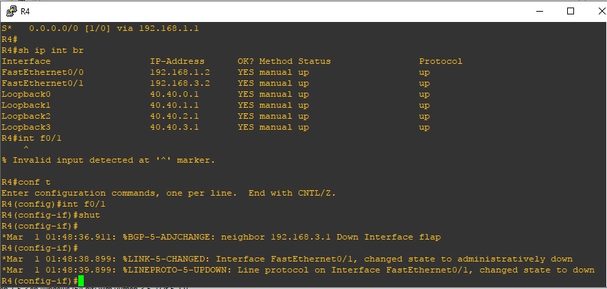
On R4, this is what our routing table will look like. No bgp routes are allowed in because of the prefix-list ABC in. We are using default route to go out.
40.0.0.0/24 is subnetted, 4 subnets
C 40.40.0.0 is directly connected, Loopback0
C 40.40.1.0 is directly connected, Loopback1
C 40.40.2.0 is directly connected, Loopback2
C 40.40.3.0 is directly connected, Loopback3
C 192.168.1.0/24 is directly connected, FastEthernet0/0
C 192.168.3.0/24 is directly connected, FastEthernet0/1
S* 0.0.0.0/0 [1/0] via 192.168.1.1
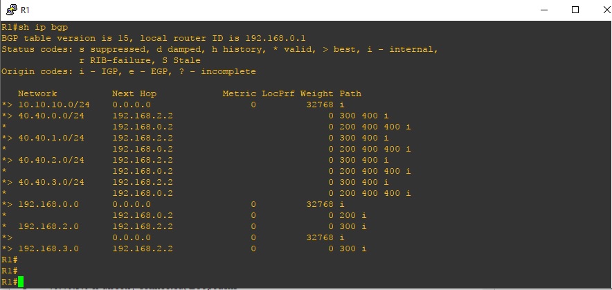
On router1:
From the output shared above, we observed that the 40.40.0.0 to 40.40.3.0 were received via ISP1 and ISP2 but ISP2 is preferred simply because we prepended the routes towards ISP1 by increasing the as-path.
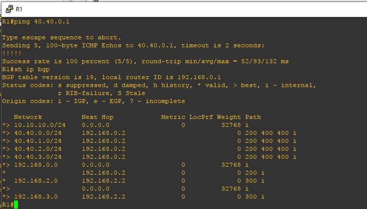
I will shutdown the link between R4 and ISP2 lets see if ISP1 will be preferred.
The next hop address for the 40 subnets, as can been seen above, has changed to 192.168.0.2 which is ISP1!!! Objective, achieved.
I know I said this is basic ebgp setup. Yes, I meant it. This is because there is so much you can do with BGP, trust me.
If you found this post helpful, please don’t forget to drop a comment and also like us on Facebook and follow us on twitter. Thank you.